Search Colleges, Exams, Schools & more


Login
To Determine Resistance Per Cm Of A Given Wire By Plotting A Graph Of Potential Difference Versus Current. - Practice Questions & MCQ
Edited By admin | Updated on Sep 18, 2023 18:34 AM | #JEE Main
Quick Facts
-

10 Questions around this concept.
Solve by difficulty
 EASY
EASYUsing Ohm's law experiment we can find the value of
Concepts Covered - 1
To determine resistance per cm of a given wire by plotting a graph of potential difference versus current.
Aim-
To determine resistance per cm of a given wire by plotting a graph of potential difference versus current.
Apparatus-
A resistance wire, a voltmeter (0-3) V and an ammeter (0-3) A of appropriate range, a battery (battery
eliminator), a rheostat, a meter scale, one-way key, connecting wires and a piece of sandpaper.
Theory-
According to Ohm's law the current flowing through a conductor is directly proportional to the potential difference across its ends provided the physical conditions (temperature, dimensions, pressure) of the conductor remain the same.
If I be the current flowing through a conductor and V be the potential difference across its ends, then according to, Ohm's Law,
$
\begin{aligned}
& I \propto V \\
& V \propto I \\
& \text { or } V=R I
\end{aligned}
$
where R is the constant of proportionality. It is known as the resistance of the conductor.
So we can use
$
R=\frac{V}{I}
$
R depends upon the nature of the material, temperature, and dimensions of the conductor.
In S.I. units, the potential difference V is measured in volt and the current lin ampere, the resistance R is measured in ohm.
(1) To establish the current-voltage relationship, it is to be shown that the ratio $\frac{V}{I}$ remains constant for a given resistance, therefore a graph between the potential difference $(\mathrm{V})$ and the current $(\mathrm{l})$ must be a straight line.
(2) The constant ratio gives unknown value of resistance, $\left(\frac{V}{I}=R\right)$
Circuit Diagram-
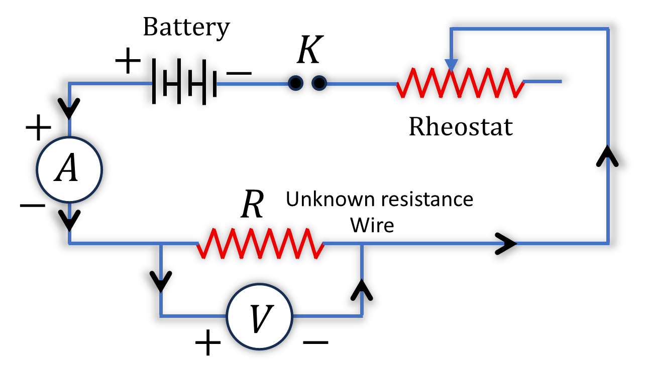
Procedure-
1. Arrange the apparatus in the same manner as given in the arrangement diagram.
2. Clean the ends of the connecting wires with sandpaper to remove the insulations, if any.
3. Make neat, clean and tight connections according to the circuit diagram. While making connections ensure that + ve marked terminals of voltmeter and ammeter are joined towards the + ve terminal of the battery.
4. Determine the least count of voltmeter and ammeter, and also note the zero error, if any.
5. Insert the key K, slide the rheostat contact and see that ammeter and voltmeter are working properly.
6. Adjust the sliding contact of the rheostat such that a measurable current passes through the resistance coil or the resistance wire.
7. Note down the value of potential difference $V$ " from voltmeter and current I from ammeter.
8. Shift the rheostat contact slightly so that both ammeter and voltmeter show full division readings and not in the fraction.
9. Record the readings of the voltmeter and ammeter.
Note- In the case of battery eliminator, follow these steps:
Turn the knob at 2 V in a battery eliminator and put the constant point in rheostat at the fixed position. Now record the reading in voltmeter and ammeter. Without disturbing the rheostat, turn the knob of battery to a different voltage such that 4,6,8,10 and 12 Volts and record corresponding readings in voltmeter and ammeter.
10. Take at least five sets of independent observations.
11. Cut the resistance wire at the points where it leaves the terminals, stretch it and find its length by the meter scale.
12. Record your observations.
Observations
1. Length
Length of the resistance wire =....
2. Range
Range of the given ammeter =....
Range of the given voltmeter =....
3. Least count
Least count of ammeter =....
Least count of voltmeter =....
4. Zero error
Zero error in ammeter, e1=....
Zero error in voltmeter, e2=....
Calculations
1. Find the ratio of V and I for each set of observations.
2. Plot a graph between potential difference V and current I, taking V along X-axis and I along Y-axis. The graph comes to be a straight line.
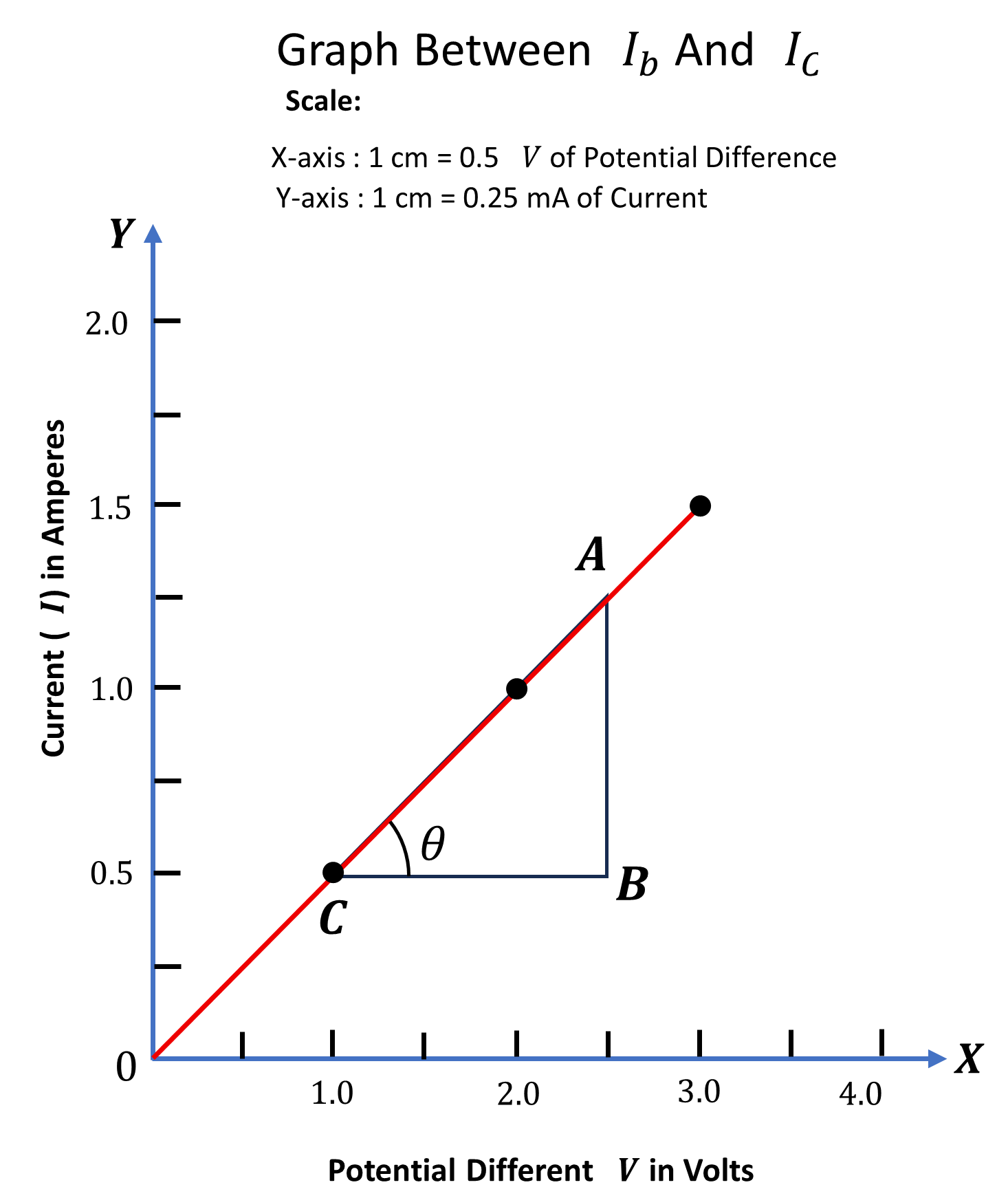
From the graph, the resistance can be calculated.
$
\begin{aligned}
& \text { in } \triangle A B C \quad \tan \theta=\frac{A B}{C B}=\frac{\Delta I}{\Delta V} \\
\Rightarrow & \cot \theta=\frac{\Delta V}{\Delta I} \\
\text { But } R & =\frac{\Delta V}{\Delta I}
\end{aligned}
$
So $R=\cot \theta$
$
R=\ldots \ldots \Omega
$
3. Constant ratio $\frac{V}{I}$ gives resistance of the wire.
4. Resistance of the wire per $\mathrm{cm}=\ldots$.
Result-
1. Resistance per cm of the wire is ......
2. The graph between V and I is a straight line.
"Stay in the loop. Receive exam news, study resources, and expert advice!"
Get Answer to all your questions
B.Tech/B.Arch Admissions OPEN
Among top 100 Universities Globally in the Times Higher Education (THE) Interdisciplinary Science Rankings 2026
UPES B.Tech Admissions 2026
ApplyLast Date to Apply Extended till Today, 30th April | Ranked #43 among Engineering colleges in India by NIRF | Highest Package 1.3 CR , 100% Placements
Amrita University B.Tech 2026
ApplyRecognized as Institute of Eminence by Govt. of India | NAAC ‘A++’ Grade | Upto 75% Scholarships
MAHE, Manipal - B.Tech Admissions 2026
ApplyExtended Application Deadline: 30th April | NAAC A++ Accredited | NIRF Rank #3
Reva University B.Tech Admissions 2026
ApplyQS I-Gauge Diamond Rated | NAAC A+ Accredited | 621 Recruitment Partners | INR 40 LPA Highest CTC | 4482 Job offers
Manav Rachna-B.Tech Admissions 2026
ApplyNAAC A++ Grade | Recognized as Category-1 Deemed to be University by UGC | 41,000 + Alumni Imprints Globally