 EASY
EASYAmity University Noida-B.Tech Admissions 2026
This round of applications closing on 15th July | Among top 100 Universities Globally in the Times Higher Education (THE) Interdisciplinary Science Rankings 2026


Motional Electromotive force(IV) is considered one the most difficult concept.
Motional Electromotive force(I), Motional Electromotive force(II), Energy consideration in Motional Emf is considered one of the most asked concept.
80 Questions around this concept.
A rectangular loop has a sliding connector PQ of length $l$ and resistance $R \Omega$ and it is moving with a speed $v$ as shown. The set-up is placed in a uniform magnetic field going into the plane of the paper. The three currents $I_1, I_2$ and $I_3$ are

A conducting square loop of side L and resistance R moves in its plane with a uniform velocity perpendicular to one of its sides. A magnetic induction B constant in time and space, pointing perpendicular and into the plane at the loop exists everywhere with half the loop outside the field, as shown in figure.

The induced emf is
In the figure shown the section EDGF is fixed. A rod having resistance ' R ' is moved with constant velocity in a uniform magnetic field B as shown in the figure. DE & FG are smooth and resistance less. Initially capacitor is uncharged. The charge on the capacitor:

JEE Main 2026: College Predictor | Official Question Papers
New: Apply to Multiple B.Tech Colleges Through Free 1:1 Counselling
Comprehensive Guide: IIT's | NIT's | IIIT's | Foreign Universities in India
A wire of length moving with velocity
at right angles to a magnetic field of
. The magnitude of induced emf, between the ends of the wire will be :
An emf of is induced in a metal rod of length
held normal to a uniform magnetic field of
, when moves with a velocity of:
A boat is moving due east in a region where the earth’s magnetic field is 5.0 × 10⁻⁵ N A-1 m-1 due north and horizontal. The boat carries a vertical aerial 2 m long. If the speed of the boat is 1.50 m s-1, the magnitude of the induced emf in the wire of the aerial is
A condenser having charge Q, capacity ‘C’ is connected with 2 smooth fixed sliders, refer to figure. Given that all the wires are resistance-less and a slender rod PR can smoothly glide on the fixed sliders. Calculate the terminal velocity of rod PR after we close the switch.

This round of applications closing on 15th July | Among top 100 Universities Globally in the Times Higher Education (THE) Interdisciplinary Science Rankings 2026
40 LPA Highest Package | Up to 100% Scholarship worth 24 Crore via GUTS exam
In the given circuit, assume the horizontal rails have negligible friction and the battery has negligible internal resistance. If the rod is released from rest, then (Resistance and mass of rod are $R_0=1 \Omega$ and $\mathrm{m}=1 \mathrm{~kg}$ respectively). Find out the time when the rod acquires half of the maximum speed. Given, $B=1 T$, length of rod $=1 \mathrm{~m}$.

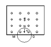
A thin circular-conducting ring having N turns of radius R is falling with its plane vertical in a horizontal magnetic field B. At the position MNQ, the speed of ring is v, the induced e.m.f. developed across the ring is
A metallic rod of length 'I' is tied to a string of length 21 and made to rotate with angular speed $\omega$ on a horizontal table with one end of the string fixed.If there is a vertical magnetic field ' B ' in the region, the e.m.f. induced across the ends of the rod is :

If a conducting rod of length $l$ is moving with a uniform velocity $\vec{V}$ perpendicular to the region of the uniform magnetic field $(\vec{B})$ which directed into the plane of the paper as shown in the below figure.

Then the magnetic force on + ve charges is given by
$
\vec{F}_B=q(\vec{v} \times \vec{B})=e(\vec{v} \times \vec{B})_{\text {toward side } \mathrm{b} .}
$
And similarly the magnetic force on -ve charges is given by $\vec{F}_B=q(\vec{v} \times \vec{B})=e(\vec{v} \times \vec{B})_{\text {toward side a }}$.
So positive and negative charges will accommodate at side $b$ and side a respectively. This will create an electric field having direction from $b$ to $a$. And electric force due to this field on charges will be given as $\vec{F}_E=q \vec{E}$
Applying Equilibrium condition between electric and magnetic force
$
F_E=F_B \Rightarrow q E=q v B \Rightarrow E=v B
$
So Potential difference induced between endpoints of the rod is given by
$
V_{a b} \equiv V_b-V_a=E L \quad \Rightarrow V_{a b}=v B L
$
this Potential difference ( $V_{a b}$ ) is known as motional emf.
So Motional EMF is given by
$
\varepsilon=B l v
$
where
$B \rightarrow$ magnetic field
$l \rightarrow$ length of conducting
$v \rightarrow$ the velocity of rod perpendicular to a uniform magnetic field.
If conducting PQ rod moves on two parallel conducting rails as shown in below figure
and we wanted to find motional emf of the moving rod

Method I-
As magnetic flux is given by $\phi=B . A$
So initial flux passing through PQRS is given by $\phi=B \cdot A=B(l . x)$
And when rod starts moving this flux will change then the change in flux is given as
$
\varepsilon=-\frac{d \phi}{d t}=-\frac{d}{d t}(B l x)=-B l \frac{d x}{d t}=-B l(-v)=B l v
$
So the motional emf is given as $\varepsilon=B l v$
Method II-
Due to the motion of the rod +ve and -ve charges of the rod will start to move towards point $Q$ and $P$ respectively.
Then the magnetic force on +ve charges is given by $\vec{F}_B=q(\vec{v} \times \vec{B})=e(\vec{v} \times \vec{B})$ toward $\mathbf{Q}$.
And similarly, the magnetic force on -ve charges is given by $\vec{F}_B=q(\vec{v} \times \vec{B})=e(\vec{v} \times \vec{B})$ toward P.
So the work done by the magnetic force to move the +ve charge from P to Q is given by $W=\vec{F}_B \cdot l=q(\vec{v} \times \vec{B}) \cdot l=q v B l$
So potential difference across PQ is given as $\Delta V=V_{P Q}=\frac{W}{q}=B l v$
So the motional emf is given as $\varepsilon=B l v$

As we learn for the above figure Motional EMF is given by
$
\varepsilon=B l v
$
where
$B \rightarrow$ magnetic field
$l \rightarrow$ length of conducting
$v \rightarrow$ the velocity of rod perpendicular to a uniform magnetic field.
So now we want to find whether the law of conservation is applicable for the motional emf or not?
So Induced Current in the conducting rod is given as $I=\frac{\varepsilon}{r}=\frac{B l v}{r}$
where $r$ is the resistance of the rod
And assuming resistance of other arms (i.e PS,SR,RQ) is negligible.
Magnetic force on conducting rod is given as
$
\begin{aligned}
& F=I l B=B\left(\frac{B l v}{r}\right) l \\
& F=\frac{B^2 v l^2}{r}
\end{aligned}
$
The power dissipated in moving the conducting rod -
$
\begin{aligned}
& P_{\text {mech }}=P_{e x t}=F \cdot v=\left(\frac{B^2 v l^2}{r}\right) \cdot v \\
& P_{\text {mech }}=P_{e x t}=\frac{B^2 l^2 v^2}{r}
\end{aligned}
$
Electric Power or the rate of heat dissipation across the resistance is given as
$
P_E=I^2 r=\left(\frac{B l v}{r}\right)^2 \cdot r=\frac{B^2 l^2 v^2}{r}
$
Since $P_{\text {mech }}=P_E$ So we can say that the principle of conservation of energy is applicable for the motional emf.
General Case-
Motional emf when $\vec{B}$ and $\vec{V}$ and $\vec{l}$ are at some angle with each other as shown in the below figure.

Then At steady state,
$
\begin{aligned}
& \text { tate, }\left|F_e\right|=\left|F_m\right| \\
& \Rightarrow F_e=-F_m \\
& \Rightarrow e \vec{E}=-\ell(\vec{V} \times \vec{B}) \\
& \Rightarrow \vec{E}=-(\vec{V} \times \vec{B})
\end{aligned}
$
$
\begin{aligned}
& \text { And Poential difference }=d v=-\vec{E} \cdot \overrightarrow{d l} \\
& \qquad \begin{aligned}
\Rightarrow d v=\int(\vec{V} \times \vec{B}) \cdot \overrightarrow{d l} \\
\Rightarrow \Delta v=(\vec{V} \times \vec{B}) \cdot \vec{l}
\end{aligned} \\
& \qquad \begin{array}{l}
\Rightarrow \quad(\vec{V} \times \vec{B}) \cdot \vec{l}
\end{array}
\end{aligned}
$
For example-

$\begin{aligned} & \text { then Induced emf } \Rightarrow \varepsilon=B l V \sin \theta \\ & \Delta v=\text { potential difference } \\ & B=\text { Magnetic field } \\ & V=\text { velocity of the rod }\end{aligned}$
Motional E.m.f due to rotational motion-
If a conducting rod $P Q$ is rotating with angular velocity $\omega$ about its one end ( $Q$ ) in a uniform magnetic field as shown in the below figure.
 then $\varepsilon=\frac{1}{2} B l^2 \omega=B l^2 \pi \nu$
where
$\nu=\frac{\omega}{2 \pi}=\frac{1}{T} \rightarrow$ frequency
$T \rightarrow$ Time period
Similarly

$\varepsilon=\frac{1}{2} B w l^2$

$\varepsilon=\frac{1}{2} B w r^2$
"Stay in the loop. Receive exam news, study resources, and expert advice!"
This round of applications closing on 15th July | Among top 100 Universities Globally in the Times Higher Education (THE) Interdisciplinary Science Rankings 2026
100+ Recruiters | 1200+ Placements of 2026 Batch | NBA & NAAC Accredited | Highest CTC 37 LPA
NAAC A++ Grade | Highest Package-30 LPA | 400+ Recruiters
NAAC A+ Grade | Ranked 503 Globally (QS World University Rankings 2026)
40 LPA Highest Package | Up to 100% Scholarship worth 24 Crore via GUTS exam
Last Date to Apply: 15th July | Ranked #43 among Engineering colleges in India by NIRF | Get Upto 100% Scholarships | Spot Admissions via CUET