Search Colleges, Exams, Schools & more


Login
To Determine The Internal Resistance Of A Primary Cell Using Potentiometer - Practice Questions & MCQ
Edited By admin | Updated on Sep 18, 2023 18:34 AM | #JEE Main
Quick Facts
-

9 Questions around this concept.
Solve by difficulty
 EASY
EASYWhy is potentiometer preferred to a voltmeter to measure voltage in a circuit
Concepts Covered - 1
To determine the internal resistance of a primary cell using potentiometer
Aim-
To determine the internal resistance of a given primary cell using a potentiometer.
Apparatus-
A potentiometer, a battery (or battery eliminator), two one-ways, a rheostat of low
resistance, a galvanometer, a high resistance box, a fractional resistance box, an ammeter,
a voltmeter, A cell say Leclanche cell, a jockey, a set square, connecting wires, and a piece
of sandpaper.
Theory-
The internal resistance of a cell is given by
$$
r=R\left[\frac{l_1-l_2}{l_2}\right]
$$
where $l_1$ and $l_2$ are the balancing lengths without shunt and with a shunt, respectively, and R is the shunt resistance in parallel with the given cell.
Circuit Diagram-
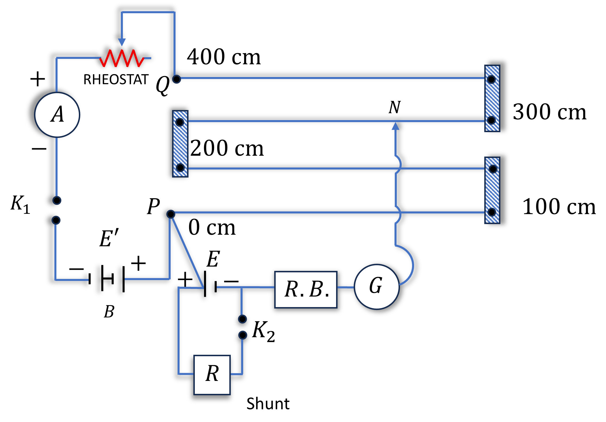
Procedure-
1. Make the connections accordingly, as shown in the circuit diagram.
2. Clean the ends of the connecting wires with sandpaper and make tight connections according to the
circuit diagram.
3. Tight the plugs of the resistance box.
4. Check the em.f. of the battery and cell and see that em.f. of the battery is more than that of the given
cell, otherwise null or balance point will not be obtained (E' > E).
5. Take maximum current from the battery, making rheostat small.
6. To test the correctness of the connections. (Insert the plug in the key $\mathrm{K}_1$ and note the ammeter reading. Take out $2000 \Omega$ resistance plug from the resistance box. Place the jockey first at the end $P$ of the wire and then at the end Q . If the galvanometer shows deflection in opposite directions in the two cases, the connections are correct).
7. Without inserting the plug in the key $\mathrm{K}_2$ adjust the rheostat so that a null point is obtained on the fourth wire of potentiometer.
8. Insert the 2000 ohm plug back in its position in resistance box and by slightly adjusting the jockey near the previously obtained position of null point, obtain the null point position accurately, using a set square.
9. Measure the balancing length $l_1$ between this point and the end P of the wire.
10. Take out the 2000 ohms plug again from the resistance box R.B. Introduce the plugs in key $\mathrm{K}_1$, as well as in key $\mathrm{K}_2$. Take out a small resistance $(1-5 \Omega)$ from the resistance box R connected in parallel with the cell.
11. Slide the jockey along the potentiometer wire and obtain null point.
12. Insert 2000 ohms plug back in its position in R.B. and if necessary make a further adjustment for sharp null point.
13. Measure the balancing length $l_1$ from end P .
14. Remove the plug keys at $\mathrm{K}_1$ and $\mathrm{K}_2$. Wait for some time and for the same value of current (as shown by the ammeter), repeat the steps 7 to 13 .
15. Repeat the observations for different values of $R$ repeating each observation twice.
16. Record your observations and on the basis of observations calculate the internal resistance.
Observations
Range of voltmeter $=\ldots$. .
Least count of voltmeter $=\ldots$. .
E.M.F. of battery (or battery eleminator) $=\ldots$. .
E.M.F. of cell $=\ldots \ldots$....
Calculations
1. For each set of observation find mean and
2. Calculate the value of r for each set.
3. Take the mean of values of r recorded.
Result
The internal resistance of the given cell is .......
"Stay in the loop. Receive exam news, study resources, and expert advice!"
Get Answer to all your questions
B.Tech/B.Arch Admissions OPEN
Among top 100 Universities Globally in the Times Higher Education (THE) Interdisciplinary Science Rankings 2026
UPES B.Tech Admissions 2026
ApplyLast Date to Apply Extended till Today, 30th April | Ranked #43 among Engineering colleges in India by NIRF | Highest Package 1.3 CR , 100% Placements
Amrita University B.Tech 2026
ApplyRecognized as Institute of Eminence by Govt. of India | NAAC ‘A++’ Grade | Upto 75% Scholarships
MAHE, Manipal - B.Tech Admissions 2026
ApplyExtended Application Deadline: 30th April | NAAC A++ Accredited | NIRF Rank #3
Reva University B.Tech Admissions 2026
ApplyQS I-Gauge Diamond Rated | NAAC A+ Accredited | 621 Recruitment Partners | INR 40 LPA Highest CTC | 4482 Job offers
Manav Rachna-B.Tech Admissions 2026
ApplyNAAC A++ Grade | Recognized as Category-1 Deemed to be University by UGC | 41,000 + Alumni Imprints Globally