Search Colleges, Exams, Schools & more


Login
To Find Resistance Of A Given Wire Using Metre Bridge And Hence Determine The Specific Resistance - Practice Questions & MCQ
Edited By admin | Updated on Sep 18, 2023 18:34 AM | #JEE Main
Quick Facts
-

20 Questions around this concept.
Solve by difficulty
 EASY
EASYIn a meter bridge experiment resistance is connected as shown in the figure. Initially resistance P=4 and the neutral point N is at 60 cm from A. Now an unknown resistance R is connected in series to P and the new position of the neutral point is at 80 cm from A.The value of unknown resistance R is :

Which material of wire is used in the meter bridge?
Concepts Covered - 1
To find resistance of a given wire using metre bridge and hence determine the specific resistance
Aim:
To find the resistance of a given wire using meter bridge and hence determine the resistivity (specific
resistance) of its material.
Apparatus:
A meter bridge, a Leclanche cell (Battery eliminator), a galvanometer, a resistance box, a jockey, a one-way key, a resistance wire, a screw gauge, a meter scale, a set square, connecting wires and a piece of sandpaper.
Theory:
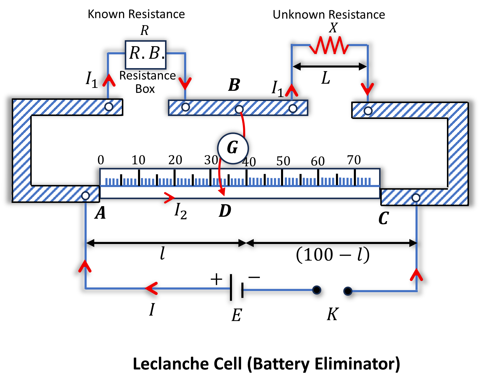
(i) The unknown resistance X is given by $X=\frac{(100-l)}{l} \cdot R$ where $R$ is known resistance placed in the left gap and unknown resistance $X$ in the right gap of the meter bridge. $l \mathrm{~cm}$ is the length of meter bridge wire from zero ends up to balance point.
(ii) Specific resistance ( $\rho$ ) of the material of the given wire is given by $\rho=\frac{X \pi D^2}{4 L}$ where $L$ is the length and $D$ is the diameter of the given wire.
Circuit Diagram-
Procedure
I.For Resistance
1. Arrange the apparatus as shown in the arrangement diagram.
2. Connect the resistance wire whose resistance is to be determined in the right gap between C and B.
Take care that no part of the wire forms a loop:
3. Connect resistance box of low range in the left-hand gap between A and B.
4. Make all the other connections as shown in the circuit diagram.
5. Take out some resistance (say 2 ohms) from the resistance box, plug the key K.
6. Touch the jockey gently first at the left end and then at the right end of the bridge wire.
7. Note the deflections in the galvanometer. If the galvanometer shows deflections in opposite
directions, the connections are correct. If the deflection is one side only, there is some fault in the
circuit. Check or take the help of your teacher and rectify the fault.
8. Move (slide) the jockey gently along the wire from left to right till the galvanometer gives zero deflection.
The point where the jockey is touching the wire is null point D.
9. Choose an appropriate value of R from the resistance box such that there is no deflection in the
galvanometer when the jockey is nearly in the middle of the wire (i.e. between 45 cm to 55 cm ).
10. Note position of point the help of a set square) to know the length AD=l
11. Take at least four sets of observations in the same way by changing the value of R in steps.
12. Record your observations.
II.For Specific Resistance
13. Cut the resistance wire at the points where it leaves the terminals, stretch it and find its length by
using a meter scale.
14. Measure the diameter of the wire at least at four places, in two mutually perpendicular directions at
each place with the help of a screw gauge.
15. Record your observations as given in tables.
Calculation-
I. Calculation for X
1. From the position of D , find $l \mathrm{~cm}$
2. Similarly, Find the length $(100-l) \mathrm{cm}$
3. Calculate $X$
4. and find
$$
\text { Mean } X=\frac{X_1+X_2+X_3+X_4}{4}=\ldots \ldots \text { ohm }
$$
II. Calculation for D
$$
\begin{aligned}
\text { Mean corrected diameter } & =\frac{D_1(a)+D_1(b)+\ldots \ldots+D_4(a)+D_4(b)}{8} \\
& =\ldots \ldots \mathrm{mm}=\ldots \ldots \mathrm{cm}
\end{aligned}
$$
III. The calculation for Specific Resistance
The specific resistance of the material of the given wire,
$$
\rho=\frac{X \pi D^2}{4 L}
$$
$\rho=\ldots \ldots$ ohm -cm
$\rho=\ldots \ldots$ ohm -m
The standard value of specific resistance of the material of the given wire (if given)
$$
\begin{aligned}
& \rho_0=\ldots \ldots \text { ohm }-\mathrm{m} \\
& \text { percentage error }=\frac{\rho-\rho_0}{\rho_0} * 100=\ldots \ldots . \%
\end{aligned}
$$
Result
1. The value of unknown resistance X=...
2. The specific resistance of the material of the given wire =
3. Percentage error =
Precautions-
1. The connections should be neat, clean and tight.
2. All the plugs in the resistance box should be tight.
3. The null point should be brought between 45 cm and 55 cm.
4. The wire should not make a loop.
Sources of error
1. The instrument screws may be loose.
2. The plugs may not be clean.
3. The wire may not have a uniform thickness.
4. The screw gauge may have faults like backlash error and wrong pitch.
Study it with Videos
"Stay in the loop. Receive exam news, study resources, and expert advice!"
Get Answer to all your questions
B.Tech/B.Arch Admissions OPEN
Among top 100 Universities Globally in the Times Higher Education (THE) Interdisciplinary Science Rankings 2026
UPES B.Tech Admissions 2026
ApplyLast Date to Apply: 30th May | Ranked #43 among Engineering colleges in India by NIRF | Highest Package 1.3 CR , 100% Placements
Amrita University B.Tech 2026
ApplyRecognized as Institute of Eminence by Govt. of India | NAAC ‘A++’ Grade | Upto 75% Scholarships | Only JEE Scores Accepted
Shoolini University Admissions 2026
ApplyNAAC A+ Grade | Ranked 503 Globally (QS World University Rankings 2026)
Manav Rachna-B.Tech Admissions 2026
ApplyNAAC A++ Grade | Recognized as Category-1 Deemed to be University by UGC | 41,000 + Alumni Imprints Globally
Quantum University Admissions 2026
Apply33.5 LPA-Highest Package | Up to 100% scholarship worth 30 CR